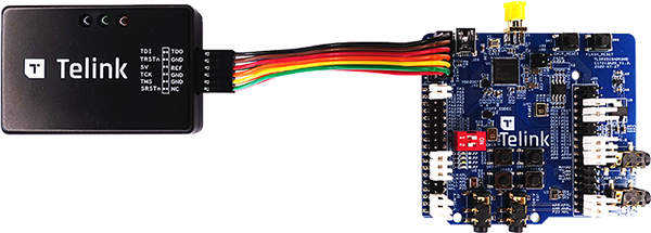
Pull docker image from repository:
$ docker pull alexkolosovtelinksemi/chip-build-telink:latest
Run docker container:
$ docker run -it -v ${CHIP_BASE}:/root/chip alexkolosovtelinksemi/chip-build-telink:latest
here ${CHIP_BASE} is directory which contains CHIP repo files !!!Pay attention that OUTPUT_DIR should conatins ABSOLUTE path to output dir
Run build script:
cd /root/chip/scripts/examples && ./telink_example.sh
Exit docker container and collect build artifacts. Firmware binary would be located in ${CHIP_BASE}/examples/lighting-app/telink/build/tlsr9518adk80d/zephyr/zephyr.bin
To make west flash command works following steps should be performed just once:
Download toolchain:
$ wget http://wiki.telink-semi.cn/tools_and_sdk/Tools/IDE/telink_riscv_linux_toolchain.zip
$ unzip telink_riscv_linux_toolchain.zip
Add TELINK_TOOLCHAIN_BASE variable to environment:
$ export TELINK_TOOLCHAIN_BASE=${PATH_TO_TOOLCHAIN}
Setup dependencies:
$ sudo dpkg --add-architecture i386
$ sudo apt-get update
$ sudo apt-get install -y libc6:i386 libncurses5:i386 libstdc++6:i386
$ cd ${TELINK_LIGHTING_EXAMPLE_DIR} && west flash
Use following manual to build your own border router: https://openthread.io/guides/border-router/build Pay attention that border router should be configured as Access Point i.e next command should be executed in step 3:
$ BORDER_ROUTING=0 NETWORK_MANAGER=1 ./script/setup
Pay attention that border router shoud be configured as IPv6 access point.
ip -6 addr add 2001:db8:1::1/64 dev wlan0
enable-ra
dhcp-range=2001:db8:1::, ra-only, 64, 12h
Use Web GUI to config Thread network tlsr9518adk80d board supports only static comissioning with predefined Thread credentials shown in table below:
| Item | Value |
|---|---|
| Network name | OpenThreadDemo |
| Network ExtendedPAN ID | 1111111122222222 |
| PAN ID | 0x1234 |
| Passphrase | 123456 |
| Master Key | 00112233445566778899aabbccddeeff |
| Channel | 15 |
| On-Mesh Prefix | fd11:22:: |
To get output from device, connect UART to following pins:
| Name | Pin |
|---|---|
| RX | PB3 (pin 17 of J34 connector) |
| TX | PB2 (pin 16 of J34 connector) |
| GND | GND |
The following buttons are available on tlsr9518adk80d board:
| Name | Function | Description |
|---|---|---|
| Button 1 | Factory reset | Perform factory reset to forget currently commissioned Thread network and back to uncommisioned state |
| Button 2 | Lighting control | Manually triggers the lighting state |
| Button 3 | Thread start | Comission thread with static credentials and enables the Thread on device |
Red LED indicates current state of Thread network. It ables to be in following states:
| State | Description |
|---|---|
| Blinks with short pulses | Device is not commisioned to Thread, Thred is disabled |
| Blinls with frequent pulses | Device is commissioned, Thread enabled. Device trying to JOIN thread network |
| Blinks with whde pulses | Device commissioned and joined to thread network as CHILD |
Blue LED shows current state of lightbulb
ping -6 ${IP_ADDRESS_OF_CHIP_DEVICE}
here ${IP_ADDRESS_OF_CHIP_DEVICE} is address which you got from UART output of tlsr9518adk80d board If everything is ok then ping command should perform transactions without lossesBuild chip-tool cli
Pair with device
${CHIP_TOOL_DIR}/chip-tool pairing bypass ${IP_ADDRESS_OF_CHIP_DEVICE} 11097
here:
${IP_ADDRESS_OF_CHIP_DEVICE} is IPv6 address of CHIP deviceSwitch on the light:
${CHIP_TOOL_DIR}/chip-tool onoff on 1
here:
Switch off the light:
${CHIP_TOOL_DIR}/chip-tool onoff off 1
here:
Read the light state:
${CHIP_TOOL_DIR}/chip-tool onoff read on-off 1
here:
Change brightness of light:
${CHIP_TOOL_DIR}/chip-tool levelcontrol move-to-level 32 0 0 0 1
here:
Reag brightness level:
./chip-tool levelcontrol read current-level 1
here: